Motorcycle tyre changer
I've long had a philosphy that I wouldn't pay someone else to do something I could do myself. Dentistry is an obvious exception :D Fitting tyres, however, is well within my scope of monkey-mechanicing. That said, I have been known to raise a sweat while grappling with black rubbery things (oo-er missus) so I decided that perhaps a little assistance might be in order. Of course you can go the whole hog and buy one of the professional machines you see in garages, and I guess if I had more space I might have been tempted to find a used one of those. Perusing a variety of designs around the internet, I found a Youtube video demonstrating a manual changer made by Olmax Motors in Poland.
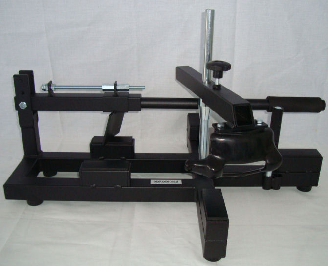
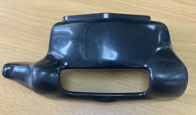
It was the sort of thing I was looking for... but not the sort of price I wanted to pay! The design looked simple enough, with just one component that would be hard to replicate: the 'duck's head', the plastic moulded part that lifts the bead of the tyre and guides it onto the rim, without itself damaging the rim. Okay then: first things first, can I find this 'duck's head' for sale anywhere? Yes I can, but even that is a bit expensive - it is of course aimed at the trade who would soon recoup the outlay. As luck would have it there was what appeared to be a private seller offering one on Ebay. It failed to attract any bids so when he relisted it I went in with an offer which was accepted... so, suddenly, the project was on!
I saved the various photos of the changer that Olmax show and began to work out what material - or rather, what size material - to use. Helpfully, they mention that the upright spindle (that passes through the wheel bearings to locate the wheel on the frame) is 20mm diameter and is screwed into a left-hand thread nut. From the photos I could then scale up from the nut size to get the dimension of the steel box-section, as well as the width between the frame rails. Side-on views were scaled using the now-known tube dimension in order to get an idea of length and width and I then fired up AutoCAD to see how it might all work. Of further assistance was the quoted maximum brake disc diameter that would fit.
Comparing the CAD with the photos suggested I had it somewhere near, so I then superimposed circles of differing diameters on the plan view to represent the range of rim sizes that might be encountered - Olmax state 14" to 22". I can't see me needing the extremes but it did look as though most would fit, just the 14" circle looked like it was a bit close to the edges of the support blocks. If I tried to move things in a bit, it then looked as though the brake disc might foul instead, so maybe I just had the 14" rim diameter a tad on the small side.
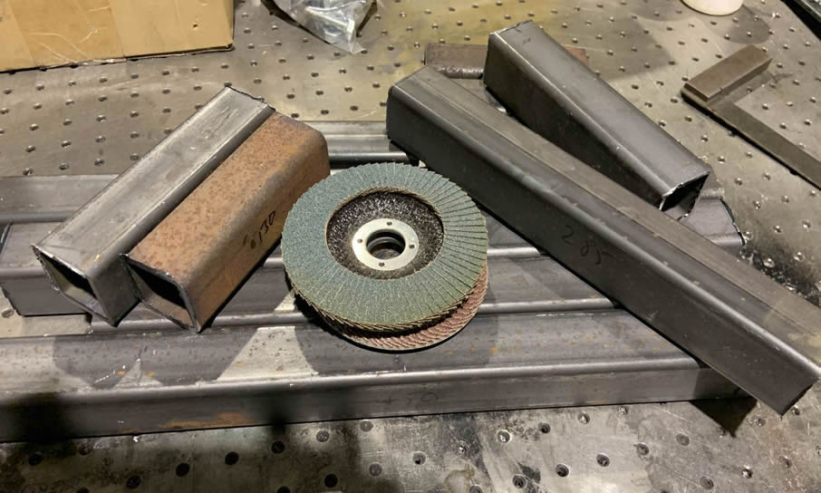
Once I was happy with the design I was able to draw up a cutting list and went off to my friendly local fabrication shop to see if they could help. And they could! I came away armed with 3m of box and some 5mm plate. Keen to make some progress, I found marker pen and engineer's square and then fired up my trusty old Bosch cut-off disc.
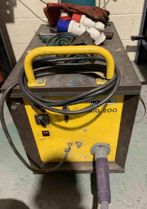
Of course in order to be able to glue the bits together, I'd need one of my welding sets. However to make space in the garage/ workshop at home I'd need to move a van, a bike and a car out and then put them away afterwards. Also, although my 120A MIG set was in the garage, the bottle of gas I needed was on another set at work! It seemed easier just to decamp to the office (the photo above was taken there, with one of the ex-Leeds University laser tables that we got for free - comes in handy as a welding bench, even if it is sacrilege! I blew the dust off my Romarc 200 (it lives at work as it needs a 32A mains supply and takes up a lot of space):
With the aid of a couple of magnets and some weighty blocks of steel I jigged the main frame parts together..
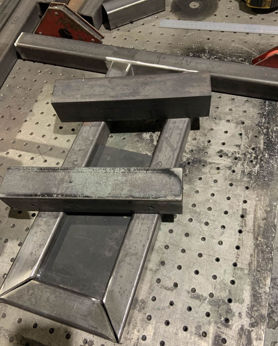
The rectangular block nestling between the side rails just happened to be 5mm wider than my calculated dimension; I decided the extra precision it gave in alignment was worth the wider gaps at the corners - not that my 45 degree cuts looked to be that accurate anyway! Some tacks were 'blobbed on'...
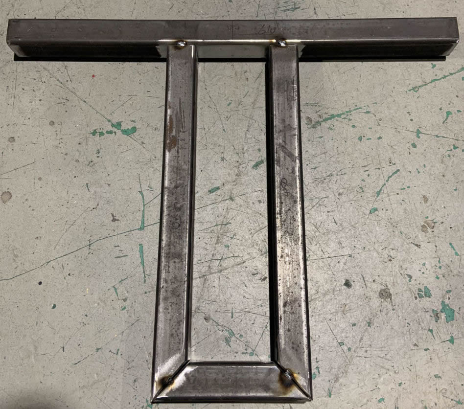
and after an hour or so of sparks, smoke and noise the main frame was beginning to look something like the drawing:
A piece of 1/4" plate was persuaded into a slightly curved shape using the press...
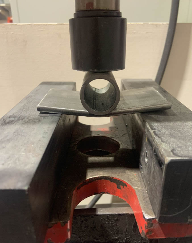
and was guessed into position under a length of box-section large enough to slide on the 40x40 of the main frame:
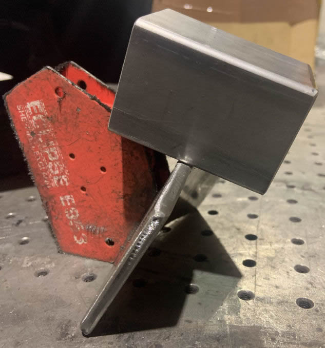
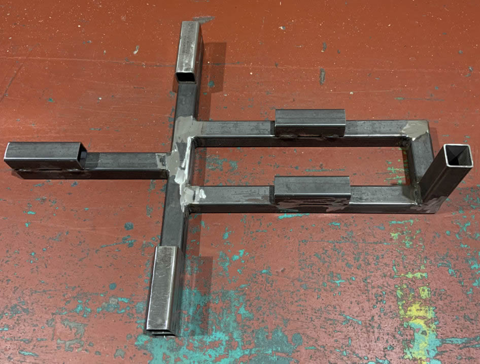
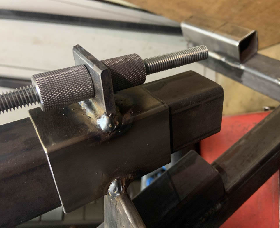
That piece forms the 'blade' of the bead breaker. It's shown below, slid onto the pivot arm. Also shown is the sliding part that will carry the aforementioned duck's head (the pivot boss at right was later TIG welded into the box):
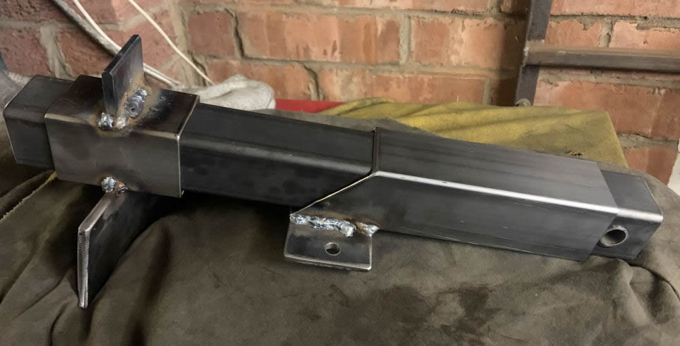
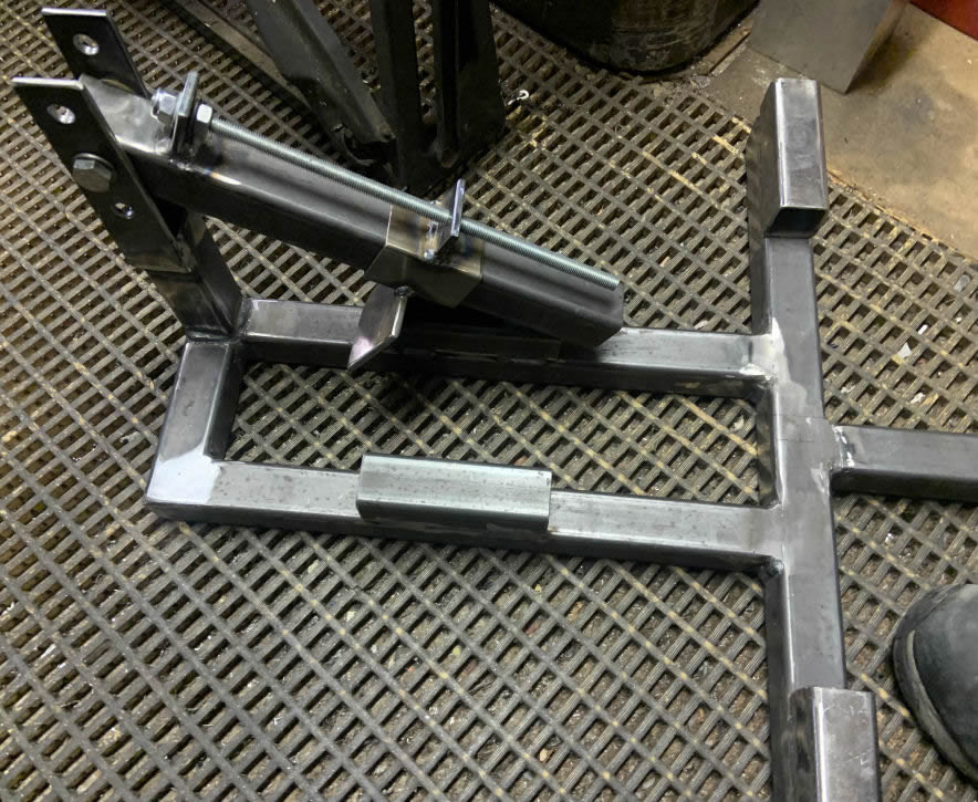
A couple of pieces of 1/4" plate were cut and drilled as a (supposedly) matching pair and then welded to the sides of the upright post on the main frame; the holes allow the bead breaker to be positioned at different heights to suit the width of the tyre being removed. A length of studding was added to provide adjustment to the breaker 'blade'...
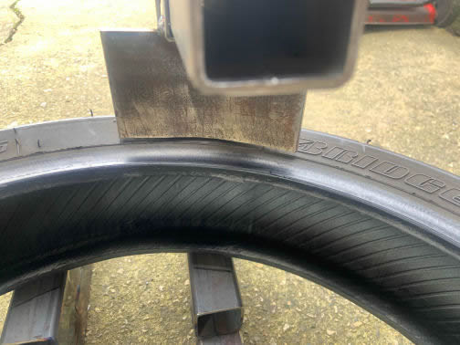
...and then it dawned on me that I have a spare front tyre lying around, which was duly pressed into service to see whether I was on the right track:
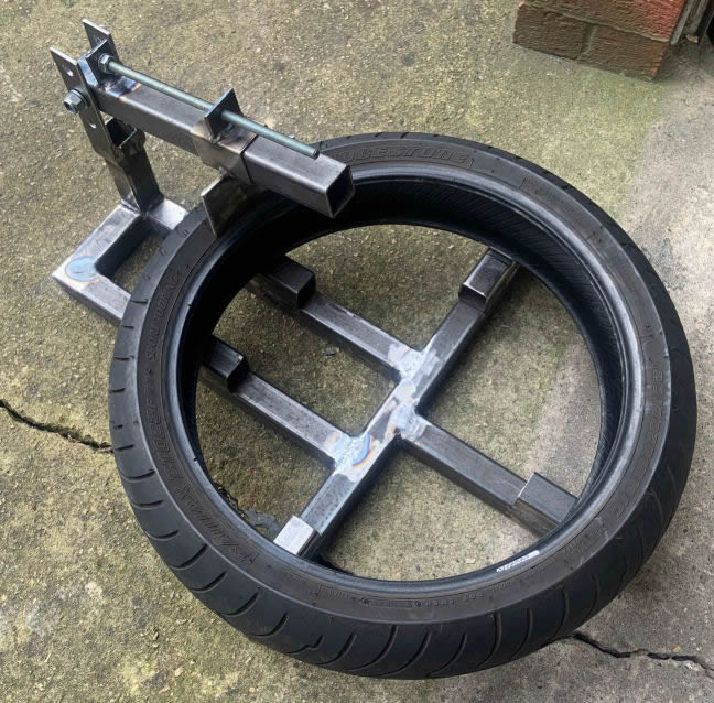
The breaker blade, as I said earlier, had been 'guessed' into position. It doesn't look too far off, although I'll probably radius the ends of the blade to prevent local stress in case the tyre is to be replaced on the rim:
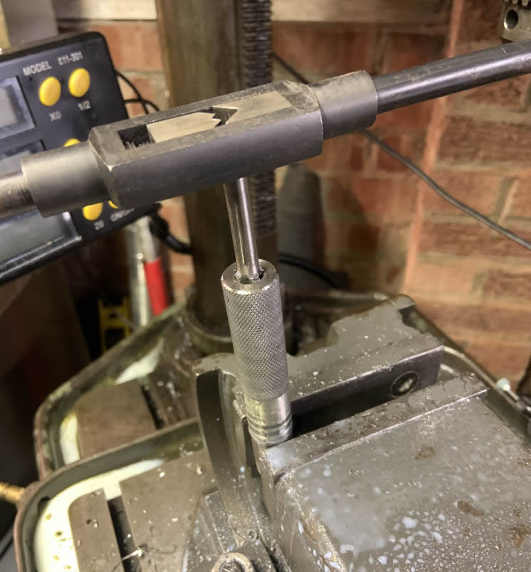
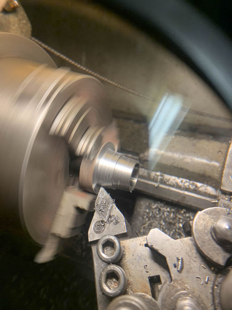
The breaker needed some nuts to secure it on the studding. Olmax's original uses a pair of long hex nuts, but I fancied a bit of lathe work so a buckshee length of round bar was knurled and then drilled through so it could be tapped:
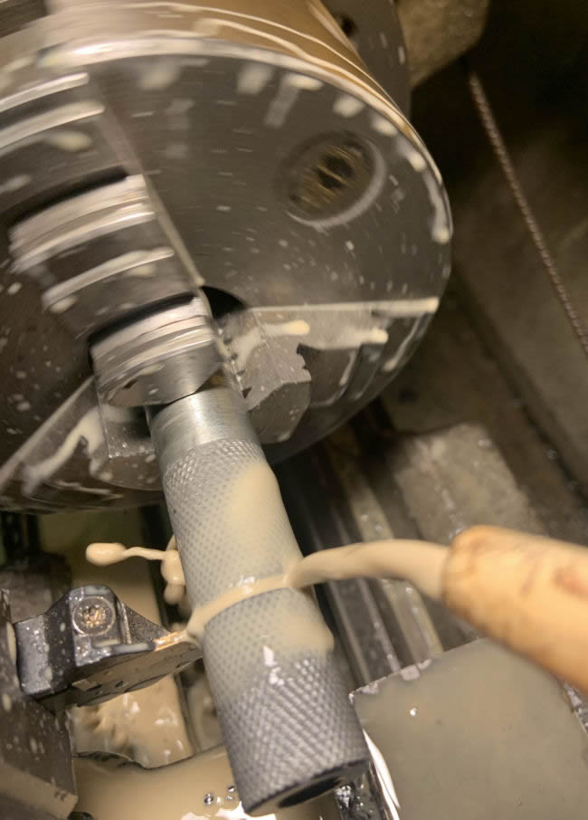
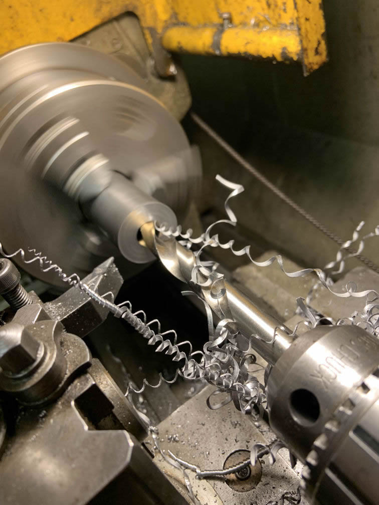
and then returned to the lathe to be parted off into two nuts.
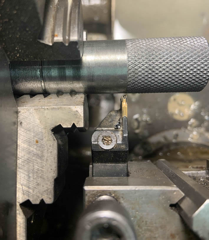
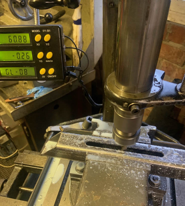
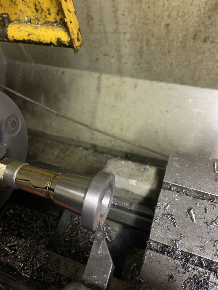
I should probably have increased the stick-out from the chuck, the parting tool shank was a bit close (below)! The marks around the bar from the chuck jaws were caused when I initially tried to tap the internal thread in the chuck - the tap snagged and turned the bar in the jaws. I finished it off in the vice as shown above - but at least it was definitely square to the bore!
The end result:
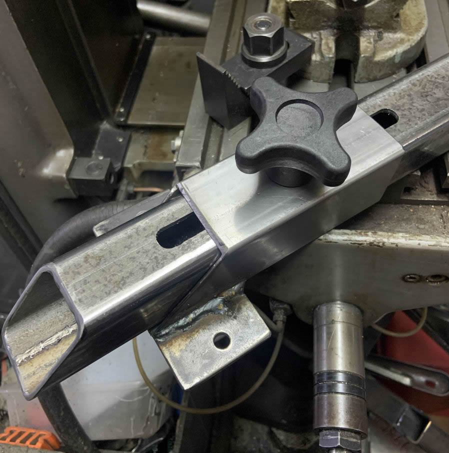
Next up was the sliding carrier for the duck's head: Olmax's version is simpler. I opted to mill a slot in the box section.
Inside the box is a piece of plate with a nut welded to it; the knob thus clamps the carrier to the arm at the appropriate radius.
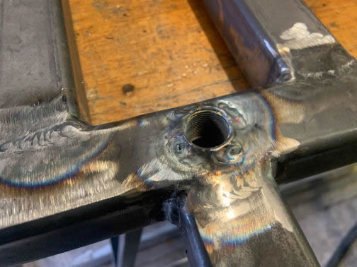
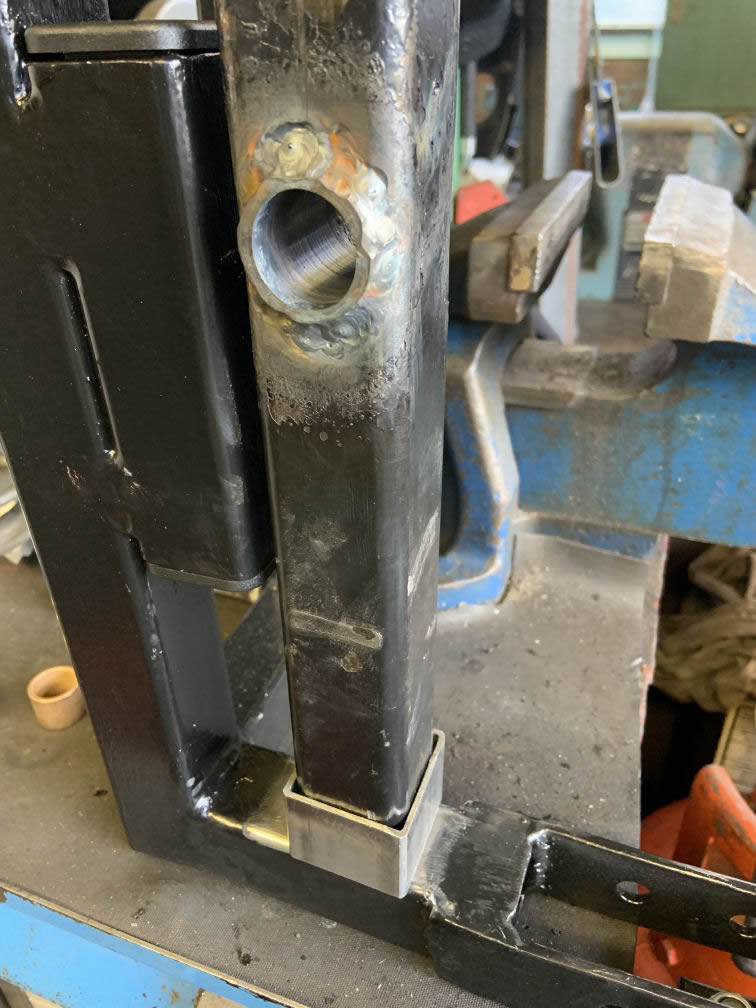
Turning to the centre post which keeps the wheel in position, I decided to replicate Olmax's 20mm left-hand thread. On their version a standard nut is welded to the top face of the box. A bit of research turned up a fine-pitch left-hand threaded boss that's intended to be welded into racing car suspension arms for rod end fitments etc. - my thinking was that it has probably twice as much thread as a standard nut. Oddly, I could get one from an Ebay seller cheaper than most fastener suppliers were selling a left-hand thread nut! A close-fitting hole was drilled (using a step- and then cone-cutter) in the box and the boss inset. I thought my chances of getting the boss square and it staying put while I welded it were similar to those of me spending a mucky weekend with Emma Bunton, so I made a plug which fitted into the other end of the boss, allowing it to sit squarely on the opposite inside wall whilst remaining slightly proud. My thinking was that if I trashed the last couple of turns of thread with the weld it could always be dressed off flush. The boss is 25mm long so plenty of thread to get hold of (unlike a nut which might have been half that width).
I popped back to my friendly local fabricators and blagged a length of tube that will slot into the breaker arm and the rotating head, to give plenty of leverage, plus a length of 20mm round bar which was screwcut at one end to screw into the left-hand threaded boss. As it's just a length of fabrication material it's not the last word in either straight or round but with a light skim in the lathe it's good enough for the purpose of locating the bike wheel on the changer frame.
Having got to this stage I was busy with other things and after a few weeks I realised the bare steel of the frame was starting to acquire light surface rust, so I hastily rubbed it down and brushed the remains of a tin of black Smoothrite over it. It's not pretty, but none of my painting ever is! I also fitted black plastic blanking caps to the majority of the open tube ends - purely cosmetic.
To move things on I decided to make a tapered bush that will locate in the hub bearing and keep the bike wheel secured on the 20mm spindle. The only thing I had that was beefy enough was a spacer left over from a van towbar. This was chucked in the lathe, the bore opened to size and a shallow taper added...
I wanted to leave a flange with enough meat on it to tap for locking screws, but of course I now had the difficulty of holding a tapered part to clean up the flanged end! As it only need a tickle I came up with the idea of using a Rawl expanding concrete anchor:
which worked surprisingly well after a bit of tweaking to minimise runout of the part. A couple of threads were drilled and tapped into the flange for locking screws.
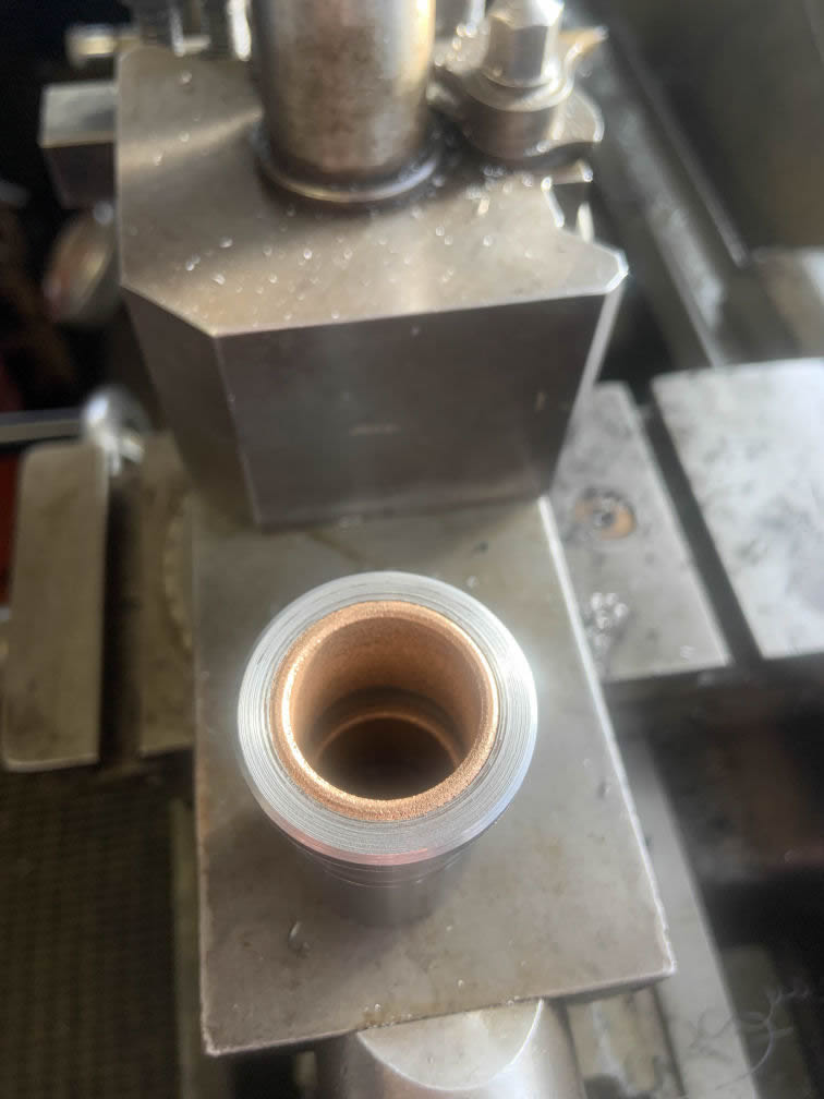
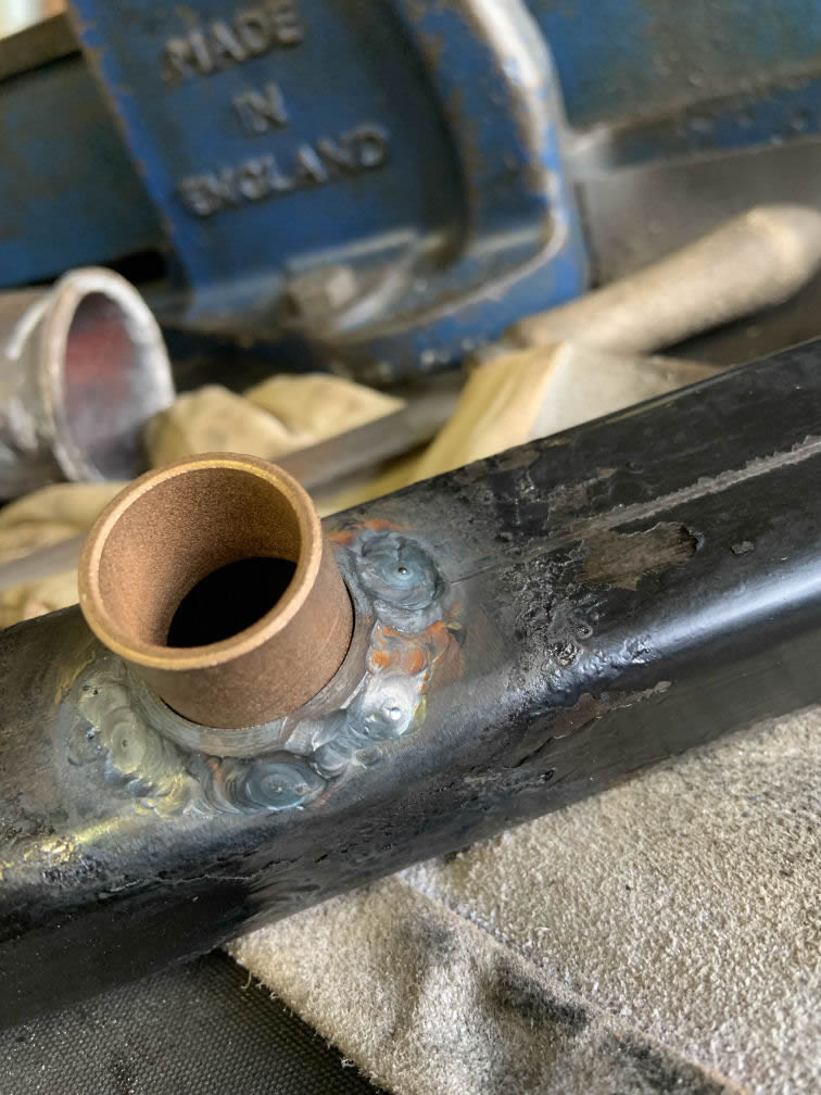
Moving to the rotating arm which actually does the work of lifting and replacing the tyre, I'd already slotted it (see above) and put a 20mm hole through the top and bottom faces so it could be slid down the upright post/ spindle. In operation this would mean the edges of the holes would bear directly on the post, probably with detrimental effect to the appearance if nothing else. Olmax do it that way so it must work, but I thought I could improve on it, if only for the experience and to spend some more money...! What I needed was a 20mm bore, but ideally with some sort of bushing. I toyed with the idea of Acetal or brass but found some Oilite bushes on Ebay: 20 ID, 24 OD and 20mm long. So to hold the bushes I needed something 24 ID and say 28 OD, and at least 40mm long. I found a place selling 32mm free-cutting mild steel bar and as luck would have it they offered a 50mm piece as a cheap sample. That arrived and was soon in the lathe chuck, being drilled and bored...
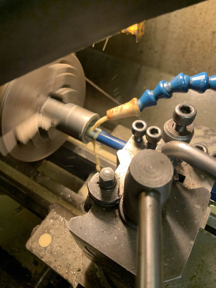
...until the Oilites were a light press fit at each end. Rather than waste time and material shortening the piece to match the 40mm of the box section I turned it down to 28mm OD, leaving a flange at one end...
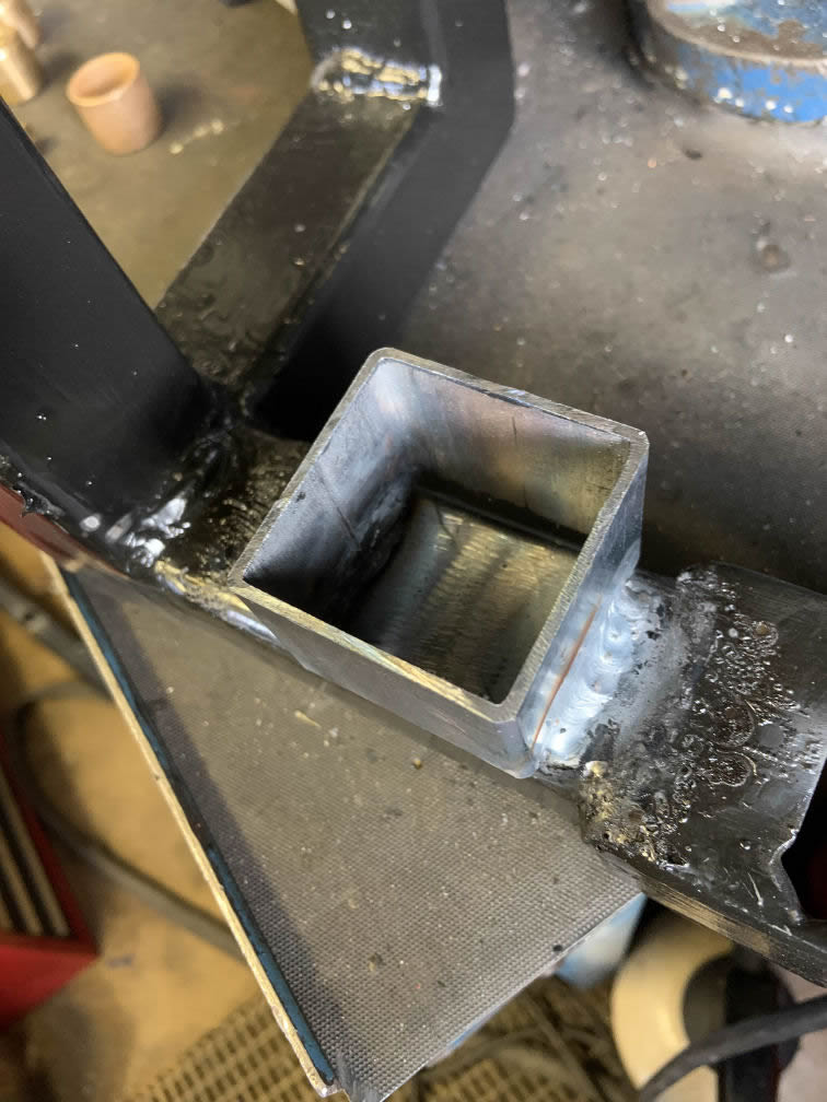
...which, once the box had been opened out to suit...
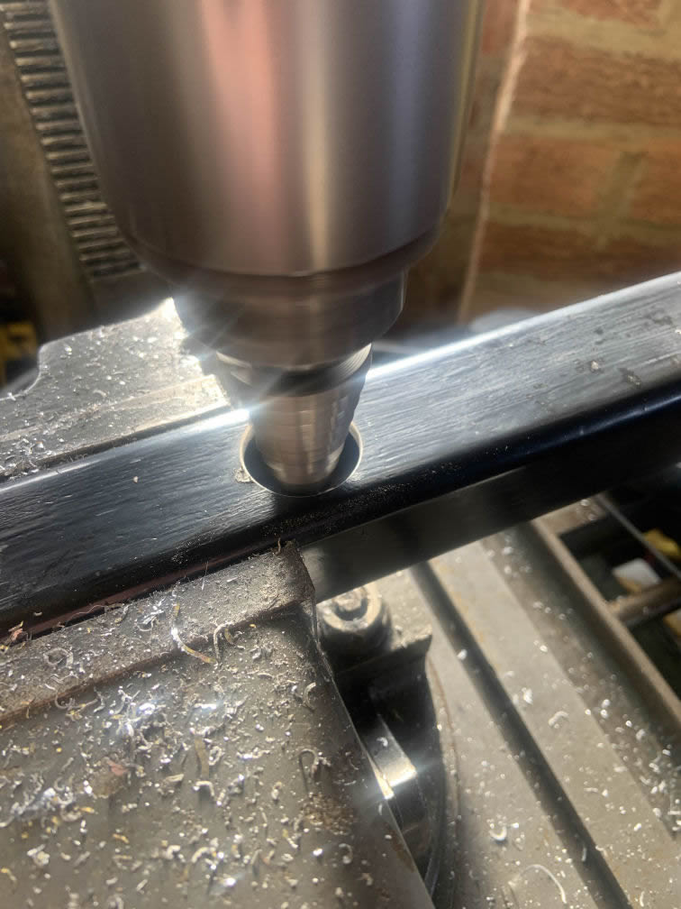
...allowed the bush to sit snugly...
... leaving plenty to get a weld on. Now a couple of tacks would have done but as usual I got carried away (and ruined the paintwork, if such was possible!) and TIG'ed all the way round both ends.
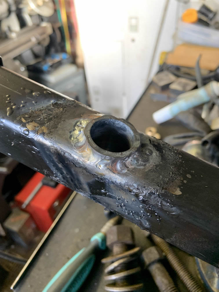
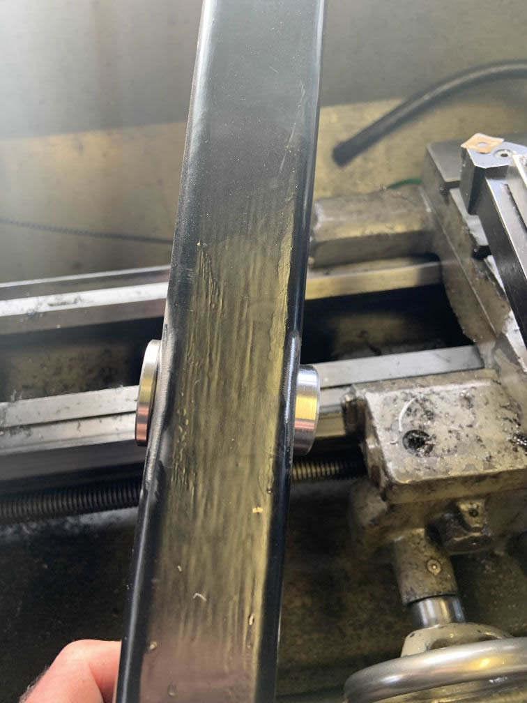
This is the reason tacks would have been better: when I tried to press the Oilites in, the bore had been pulled out of round:
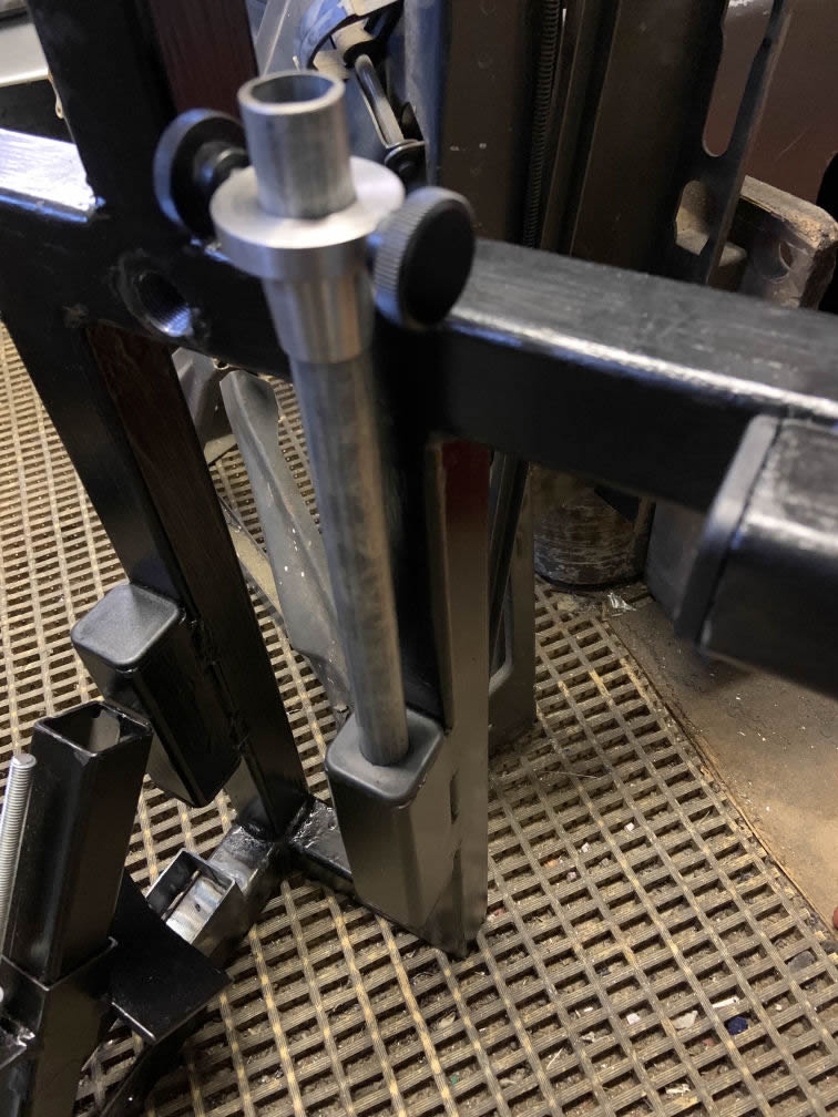
and had to be dressed with a drum abrasive in the Dremel. Eventually though, the Oilites were in. Meanwhile I'd been wondering how best to store all the bits of this tyre changer, since I have nowhere to leave it set up. Standing the main frame on end seemed a good way forward so I welded the last offcut of 45mm box (from the sliding head part) onto the frame such that the rotating arm could be slotted in, with the duck's head tucked away:
A cunningly-placed 20mm hole in one of the frame end caps provides stowage for the wheel post, seen here with the finished tapered wheel retainer and its locking screws:
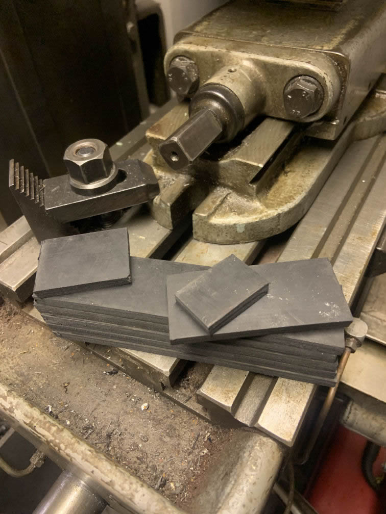
Some 6mm rubber sheet (as specified by Olmax!) was cut and glued to the appropriate areas of the frame:
To be continued...